Wind Speed Measurement and Instrumentation
Instrumentation for wind energy applications is an important subject and has been discussed in detail by numerous authors. In addition, the performance test codes for wind turbines of the American Society of Mechanical Engineers and the measurement standards of the American Wind Energy Association contain much useful information on wind instrumentation equipment and procedures.
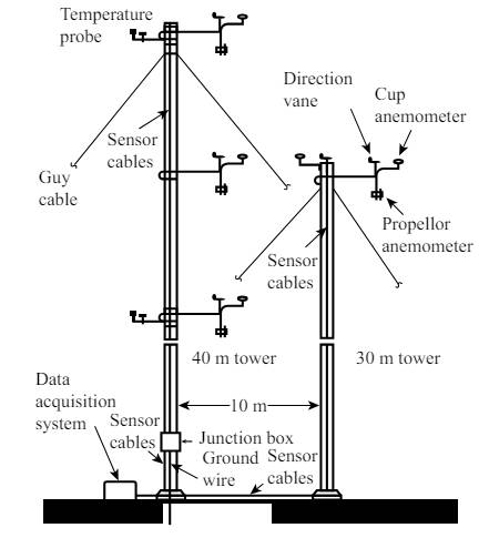
For each wind energy application, the type and amount of instrumentation required varies widely. For example, this can vary from a simple system just containing one wind speed anemometer/recorder to a very complex system designed to characterize turbulence across the rotor plane. Figure below shows an example of the latter type of system developed by PNL. This system consisted of two towers and eight anemometers, with data sampled at a rate of 5 Hz.
Wind energy applications use the following types of meteorological sensors:
The sensors of wind-measuring instrumentation can be classified according to their principle of operation via the following:
The cup anemometer is probably the most common instrument for measuring the wind speed. Cup anemometers use their rotation, which varies in proportion to the wind speed, to generate a signal. Today’s most common designs feature three cups mounted on a small shaft. The rate of rotation of the cups can be measured by:
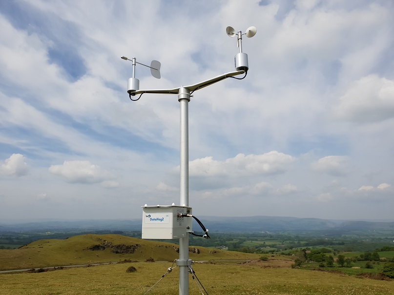
An electronic cup anemometer gives a measurement of instantaneous wind speed. The lower end of the rotating spindle is connected to a miniature AC or DC generator and the analog output is converted to wind speed via a variety of methods.
The photoelectric switch type has a disc containing up to 120 slots and a photocell. The periodic passage of the slots produces pulses during each revolution of the cup.
The response and accuracy of a cup anemometer are determined by its weight, physical dimensions, and internal friction. By changing any of these parameters, the response of the instrument will vary. If turbulence measurements are desired, small, lightweight, low-friction sensors should be used. Typically, the most responsive cups have a distance constant of about 1 m. Where turbulence data are not required, the cups can be larger and heavier, with distance constants from 2 to 5 m. This limits the maximum usable data sampling rate to no greater than once every few seconds. Typical accuracy values (based on wind tunnel tests) for cup anemometers are about +-2%.
Environmental factors can affect cup anemometers and reduce their reliability. These include ice or blowing dust. Dust can lodge in the bearings, causing an increase in friction and wear and reducing anemometer wind speed readings. If an anemometer ices up, its rotation will slow, or completely stop, causing erroneous wind speed signals, until the sensor thaws completely. Heated cup anemometers can be used, but they require a significant source of power. Because of these problems, the assurance of reliability for cup anemometers depends on calibration and service visits. The frequency of these visits depends on the site environment and the value of the data.
One commonly used anemometer in the wind industry is the Maximum cup anemometer. The sensor is about 15 cm in diameter. This anemometer has a generator that provides a sine wave voltage output. It has a Teflon sleeve bushing bearing system that is not supposed to be affected by dust, water, or lack of lubrication. The frequency of the sine wave is related to the wind speed. Special anemometers based on this design (16 pole magnet) can be used for some turbulence measurements with a 1 Hz sampling rate.
Propeller Anemometers
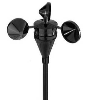 Propeller anemometers use the wind blowing into a propeller to turn a shaft that drives an AC or DC (most common) generator, or a light chopper to produce a pulse signal. The designs used for wind energy applications have a fast response and behave linearly in changing wind speeds. In a typical horizontal configuration, the propeller is kept facing the wind by a tail-vane, which also can be used as a direction indicator. The accuracy of this design is about 2%, similar to the cup anemometer. The propeller is usually made of polystyrene foam or polypropylene. The problems of reliability of propeller anemometers are similar to those discussed for cup anemometers.
For each wind energy application, the type and amount of instrumentation required varies widely. For example, this can vary from a simple system just containing one wind speed anemometer/recorder to a very complex system designed to characterize turbulence across the rotor plane. Figure below shows an example of the latter type of system developed by PNL. This system consisted of two towers and eight anemometers, with data sampled at a rate of 5 Hz.

Wind energy applications use the following types of meteorological sensors:
- Anemometers to measure wind velocity;
- Wind vanes to measure wind direction;
- Thermometers to measure the ambient air temperature;
- Barometers to measure the air pressure.
The sensors of wind-measuring instrumentation can be classified according to their principle of operation via the following:
- Momentum transfer – cups, propellers, and pressure plates;
- Pressure on stationary sensors – pitot tubes and drag spheres;
- Heat transfer – hot wires and hot films;
- Doppler effects – acoustics and laser;
- Special methods – ion displacement, vortex shedding, etc.
- Cup anemometers;
- Propeller anemometers;
- Sonic anemometers;
- Acoustic Doppler sensors (SODAR).
The cup anemometer is probably the most common instrument for measuring the wind speed. Cup anemometers use their rotation, which varies in proportion to the wind speed, to generate a signal. Today’s most common designs feature three cups mounted on a small shaft. The rate of rotation of the cups can be measured by:
- Mechanical counters registering the number of rotations;
- Electrical or electronic voltage changes (AC or DC);
- A photoelectric switch.

An electronic cup anemometer gives a measurement of instantaneous wind speed. The lower end of the rotating spindle is connected to a miniature AC or DC generator and the analog output is converted to wind speed via a variety of methods.
The photoelectric switch type has a disc containing up to 120 slots and a photocell. The periodic passage of the slots produces pulses during each revolution of the cup.
The response and accuracy of a cup anemometer are determined by its weight, physical dimensions, and internal friction. By changing any of these parameters, the response of the instrument will vary. If turbulence measurements are desired, small, lightweight, low-friction sensors should be used. Typically, the most responsive cups have a distance constant of about 1 m. Where turbulence data are not required, the cups can be larger and heavier, with distance constants from 2 to 5 m. This limits the maximum usable data sampling rate to no greater than once every few seconds. Typical accuracy values (based on wind tunnel tests) for cup anemometers are about +-2%.
Environmental factors can affect cup anemometers and reduce their reliability. These include ice or blowing dust. Dust can lodge in the bearings, causing an increase in friction and wear and reducing anemometer wind speed readings. If an anemometer ices up, its rotation will slow, or completely stop, causing erroneous wind speed signals, until the sensor thaws completely. Heated cup anemometers can be used, but they require a significant source of power. Because of these problems, the assurance of reliability for cup anemometers depends on calibration and service visits. The frequency of these visits depends on the site environment and the value of the data.
One commonly used anemometer in the wind industry is the Maximum cup anemometer. The sensor is about 15 cm in diameter. This anemometer has a generator that provides a sine wave voltage output. It has a Teflon sleeve bushing bearing system that is not supposed to be affected by dust, water, or lack of lubrication. The frequency of the sine wave is related to the wind speed. Special anemometers based on this design (16 pole magnet) can be used for some turbulence measurements with a 1 Hz sampling rate.
Propeller Anemometers
 Propeller anemometers use the wind blowing into a propeller to turn a shaft that drives an AC or DC (most common) generator, or a light chopper to produce a pulse signal. The designs used for wind energy applications have a fast response and behave linearly in changing wind speeds. In a typical horizontal configuration, the propeller is kept facing the wind by a tail-vane, which also can be used as a direction indicator. The accuracy of this design is about 2%, similar to the cup anemometer. The propeller is usually made of polystyrene foam or polypropylene. The problems of reliability of propeller anemometers are similar to those discussed for cup anemometers.
When mounted on a fixed vertical arm, the propeller anemometer may be used for measuring the vertical wind component. A configuration for measuring three components of wind velocity is shown in figure on the right side. The propeller anemometer responds primarily to wind parallel to its axis, and the wind perpendicular to the axis has no effect.
Sonic Anemometers
Sonic anemometers were initially developed in the 1970s. They use ultrasonic sound waves to measure wind speed and direction. Wind velocity is measured based on the time of flight of sonic pulses between pairs of transducers.
One-, two-, or three-dimensional flow can be measured via signals from pairs of transducers. Typical wind engineering applications use two- or three-dimensional sonic anemometers. The spatial resolution is determined by the path length between transducers (typically 10 to 20 cm). Sonic anemometers can be used for turbulence measurements with fine temporal resolution (20 Hz or better).
Acoustic Doppler Sensors (SODAR)
SODAR (standing for SOund Detection And Ranging) is classified as a remote sensing system, since it can make measurements without placing an active sensor at the point of measurement. Since such devices do not need tall (and expensive) towers for their use, the potential advantages of their use are obvious. Remote sensing is used extensively for meteorological and aerospace purposes, but only in recent times has it been used for wind siting and performance measurements.
SODAR is based on the principle of acoustic backscattering. In order to measure the wind profile with SODAR, acoustic pulses are sent vertically and at a small angle to the vertical. For measurement of three-dimensional wind velocity, at least three beams in different directions are needed. The acoustic pulse transmitted into the air experiences backscattering from particles or fluctuations in the refractive index of air. These fluctuations can be caused by wind shear as well as by temperature and humidity gradients. The acoustic energy scattered back to the ground is then collected by microphones. Assuming that the sender and the receiver are not separated, the SODAR configuration is referred to as a monostatic SODAR. At the present time all commercial SODARs used for wind energy applications are monostatic (simplifying the system design and reducing its size).
If the local speed of sound is known, the travel time between emission and reception determines the height the signal represents. A change in the acoustic frequency of the echo (Doppler shift) occurs if the scattering medium has a component of motion parallel to the beam motion. Thus, estimation of the speed of the wind speed parallel to the beam as a function of height can be carried out via frequency spectrum analysis of the received back-scattered signal.
SODARs have been used for both onshore and offshore wind siting studies with measurement of wind speed up to 300 m above the device. There has been a great deal of development on these devices over the last several years, and they are now commercially available from a number of sources. Although SODAR systems can be commercially purchased, the following issues have arisen:
- For wind energy applications, stricter requirements exist for uncertainty, reliability, and validity of the data than for other SODAR applications. For example, more work is needed on filtering techniques for data analysis.
- A general procedure for calibration of SODAR systems has not been established.
- Low wind speeds (below 4 m/s), high wind speeds (above 18 m/s), and other atmospheric phenomena can cause difficulty with SODAR measurements. This is especially important because power curve determination requires measurement of wind speeds up to the cut-out wind speed, typically around 25 m/s.
- SODAR systems have been designed for use on land. For offshore applications problems associated with vibrations from supporting structures and an increased level of background noise have to be addressed.
- SODAR is designed to send a nearly vertical beam, and to use SODAR for the detection of oncoming gusts will require a near horizontal beam.
- ODAR systems have primarily been used at sites with easy access for maintenance and noncomplex terrain. For wind energy applications at remote sites, and in complex terrain, autonomous SODAR systems will need further development, especially in areas of power supply and data communication.
Post a Comment:
You may also like:
Featured Articles
What is Wind Energy?
 Wind is moving air. We can use the energy in wind to do work. Early Egyptians used the wind to sail ships on the Nile River. ...
 Wind is moving air. We can use the energy in wind to do work. Early Egyptians used the wind to sail ships on the Nile River. ...
Wind Farm Siting, Installation and ...
 Before wind turbines can be installed, the most appropriate location or locations for them needs to be determined. The ...
 Before wind turbines can be installed, the most appropriate location or locations for them needs to be determined. The ...
Basics of Wind Energy Production
 In the United States, most wind energy is commercially generated for delivery and sale on the grid. Wind projects vary in ...
 In the United States, most wind energy is commercially generated for delivery and sale on the grid. Wind projects vary in ...
Basics of Wind Farms
 Throughout history, wind has been used to move grain mills or push the vessels that sailed the seas. However, it was not ...
 Throughout history, wind has been used to move grain mills or push the vessels that sailed the seas. However, it was not ...
What is a Capacity Factor?
 Wind turbines convert the kinetic energy in moving air into rotational energy, which in turn is converted to ...
 Wind turbines convert the kinetic energy in moving air into rotational energy, which in turn is converted to ...